Details
1. create new project on QFSM.
Select File -> New
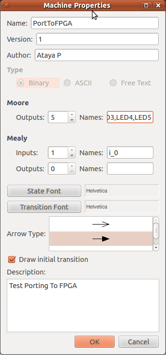
2. Enter initial setting values as image below.
We use Moore's model for a design. so, at Moore: Outputs enter LED1,LED2,LED3,LED4,LED5
These are output LED pins on the FPGA board.
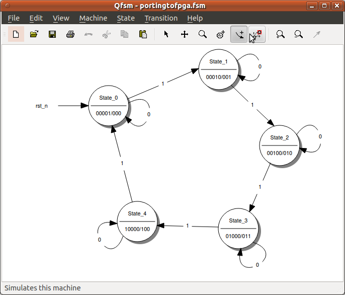
3. Creating state machine diagram as image below.
At State properties, on Moore [Outputs] enter LEDs value you prefer.
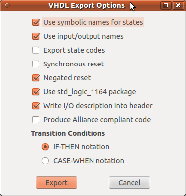
4. After check you design. Then export it into VHDL code.
Select File->Export->VHDL
I use default setting.Just click on Export button.
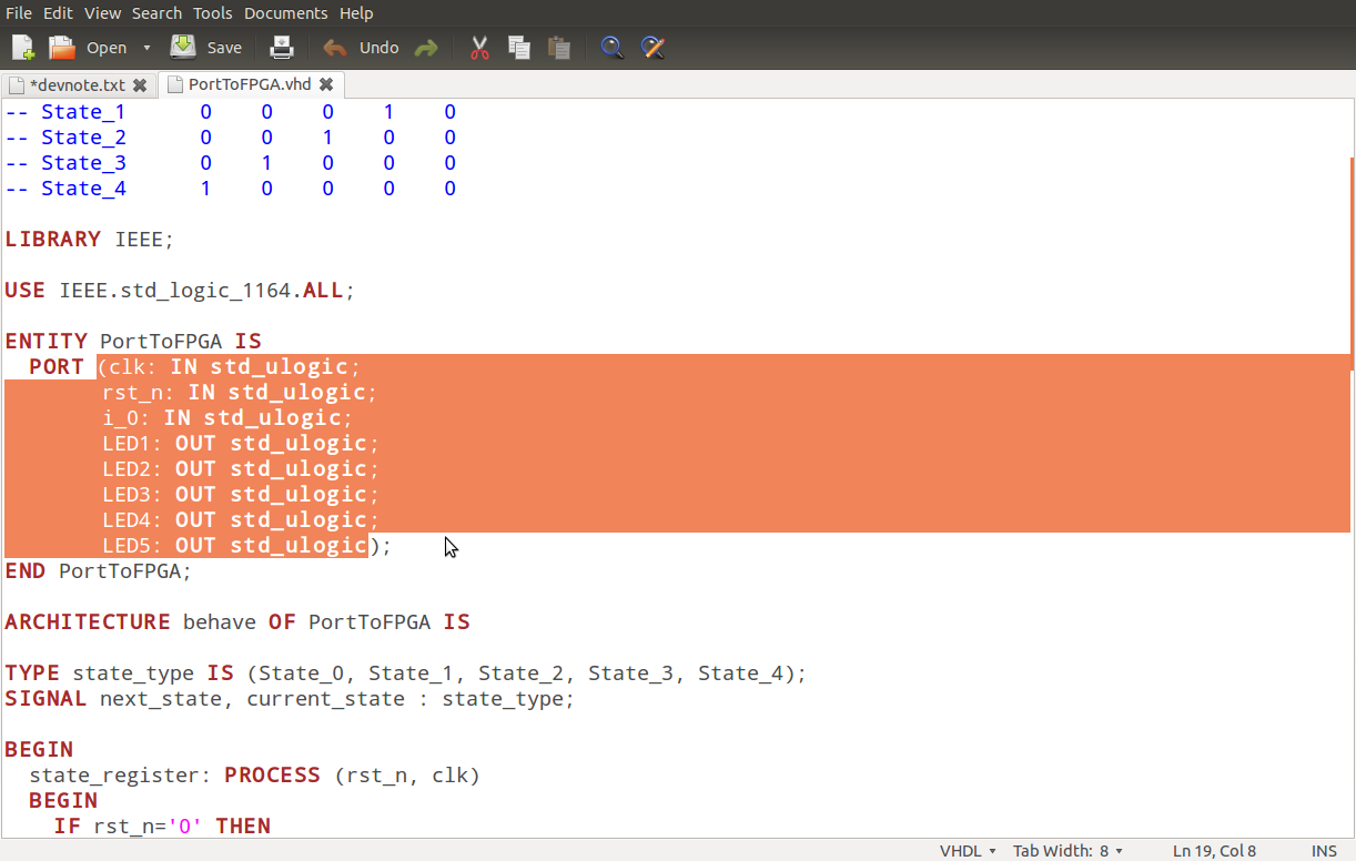
5. Save VHDL file as PortToFPGA.vhd
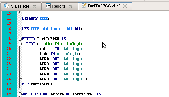
6.Take a look at the file, you will see the PORT that we need to mapping them with the FPGA pins.
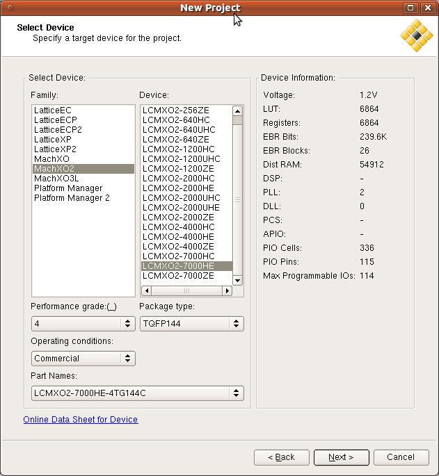
7.Now execute Diamond,create new project for your MachXO2 breakout board.
8.Add PortToFPGA.vhd into input files.
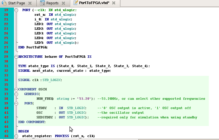
9.In this example, we will use internal oscillator. So, just comment out CLK port.
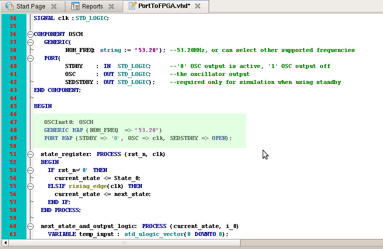
10.Then add signal clk instead and define to use OSCH component.
11.At the point before state_register process begin, add the code to mapping clk signal with internal oscillator.
12.Run the synthesize process one time. Check for errors. It should have 0 error.
13.Then open Tool-> Spreadsheet View and enter pins that you want to connect. Save the pin assign file.(the rst_n pin should set as pull up. the others are pull down)
The pins assignment file should be like this...
BLOCK RESETPATHS ;
BLOCK ASYNCPATHS ;
LOCATE COMP "LED1" SITE "97" ;
LOCATE COMP "LED2" SITE "98" ;
LOCATE COMP "LED3" SITE "99" ;
LOCATE COMP "LED4" SITE "100" ;
LOCATE COMP "LED5" SITE "104" ;
LOCATE COMP "i_0" SITE "69" ;
LOCATE COMP "rst_n" SITE "68" ;
IOBUF PORT "rst_n" PULLMODE=UP IO_TYPE=LVCMOS33 ;
IOBUF PORT "i_0" PULLMODE=DOWN IO_TYPE=LVCMOS33 ;
IOBUF PORT "LED1" PULLMODE=DOWN IO_TYPE=LVCMOS33 ;
IOBUF PORT "LED2" PULLMODE=DOWN IO_TYPE=LVCMOS33 ;
IOBUF PORT "LED3" PULLMODE=DOWN IO_TYPE=LVCMOS33 ;
IOBUF PORT "LED4" PULLMODE=DOWN IO_TYPE=LVCMOS33 ;
IOBUF PORT "LED5" PULLMODE=DOWN IO_TYPE=LVCMOS33 ;
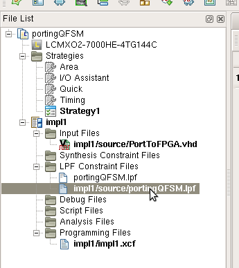
14.Add portingQFSM.lpf and set it as Active Preference File.
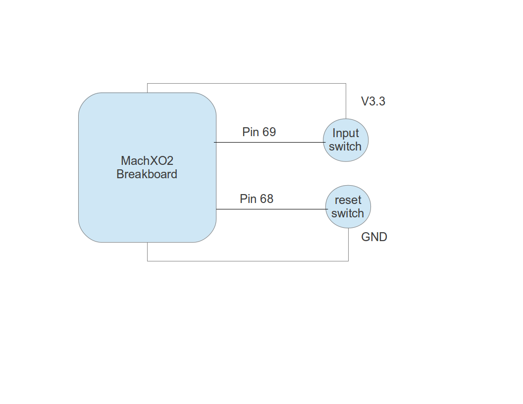
15.Connect FPGA board with two switches. One is for input and the other is for reset. As image below.
16.Generate JEDEC file and download it into the breakboard.